Blog number:-015
Hello everybody,
Well, I hope you all will be fine.
Today, we are going to discuss about one of the most basic concept of electricity, i.e. Series and Parallel circuits. It's application is everywhere in the field of Electrical and Electronics.
Introduction:-

Circuits consisting of just one battery and one load resistance are very simple to analyze, but they are not often found in practical applications. Usually, we find circuits where more than two components are connected together. There are two basic ways in which the components of an electric circuits(such as Resistor, Inductor, Capacitor) can be connected.
1). Series Connection
2). Parallel Connection
1). Series Connection
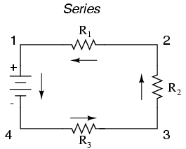
In a series circuit, the current through each of the components is the same, and the voltage across the circuit is the sum of the voltages across each component. With simple series circuits, all components are connected end-to-end to form only one path for electrons to flow through the circuit.
Here, we have three resistors (labeled R1, R2, and R3), connected in a long chain from one terminal of the battery to the other. (It should be noted that the subscript labeling—those little numbers to the lower-right of the letter “R”—are unrelated to the resistor values in ohms. They serve only to identify one resistor from another.) The defining characteristic of a series circuit is that there is only one path for electrons to flow.
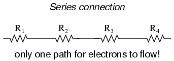
The basic idea of a “series” connection is that components are connected end-to-end in a line to form a single path for electrons to flow:
Series circuits are sometimes called current-coupled or daisy chain-coupled.
Current
The current in a series circuit goes through every component in the circuit. Therefore, all of the components in a series connection carry the same current. There is only one path in a series circuit in which the current can flow.

In a series circuit the current is the same for all of the elements.
Resistors
The total resistance of resistors in series is equal to the sum of their individual resistances:


Inductors
Inductors follow the same law, in that the total inductance of non-coupled inductors in series is equal to the sum of their individual inductances:


Capacitor
Capacitors follow the same law using the reciprocals. The total capacitance of capacitors in series is equal to the reciprocal of the sum of the reciprocals of their individual capacitances:

- .

Switches
Two or more switches in series form a logical AND; the circuit only carries current if all switches are closed.
Cells and batteries
A battery is a collection of electrochemical cells. If the cells are connected in series, the voltage of the battery will be the sum of the cell voltages. For example, a 12 volt car battery contains six 2-volt cells connected in series. Some vehicles, such as trucks, have two 12 volt batteries in series to feed the 24 volt system.
2). Parallel Connection
In parallel circuits, all components are connected between the same two sets of electrically common points, creating multiple paths for electrons to flow from one end of the battery to the other.In a parallel circuit, the voltage across each of the components is the same, and the total current is the sum of the currents through each component.
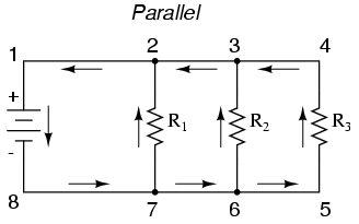
Here, we have three resistors, but this time they form more than one continuous path for electrons to flow. There’s one path from 8 to 7 to 2 to 1 and back to 8 again. There’s another from 8 to 7 to 6 to 3 to 2 to 1 and back to 8 again. And then there’s a third path from 8 to 7 to 6 to 5 to 4 to 3 to 2 to 1 and back to 8 again. Each individual path (through R1, R2, and R3) is called a branch.
The defining characteristic of a parallel circuit is that all components are connected between the same set of electrically common points. Looking at the schematic diagram, we see that points 1, 2, 3, and 4 are all electrically common. So are points 8, 7, 6, and 5. Note that all resistors as well as the battery are connected between these two sets of points.
The basic idea of a “parallel” connection is that all components are connected across each other’s leads. There are many paths for electrons to flow, but only one voltage across all components:
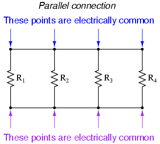
If two or more components are connected in parallel they have the same potential difference (voltage) across their ends. The potential differences across the components are the same in magnitude, and they also have identical polarities. The same voltage is applicable to all circuit components connected in parallel. The total current is the sum of the currents through the individual components .
Voltage
In a parallel circuit the voltage is the same for all elements.

Current
The current in each individual resistor is found by Ohm's law. Factoring out the voltage gives
- .

Resistors
To find the total resistance of all components, add the reciprocals of the resistances of each component and take the reciprocal of the sum. Total resistance will always be less than the value of the smallest resistance:


- .

Inductors
Inductors follow the same law, in that the total inductance of non-coupled inductors in parallel is equal to the reciprocal of the sum of the reciprocals of their individual inductances:

- .

Capacitors
The total capacitance of capacitors in parallel is equal to the sum of their individual capacitances:

- .

The working voltage of a parallel combination of capacitors is always limited by the smallest working voltage of an individual capacitor.
Switches
Two or more switches in parallel form a logical OR; the circuit carries current if at least one switch is closed.
Cells and batteries
If the cells of a battery are connected in parallel, the battery voltage will be the same as the cell voltage but the current supplied by each cell will be a fraction of the total current. For example, if a battery comprises four identical cells connected in parallel and delivers a current of 1 ampere. Some solar electric systems have batteries in parallel to increase the storage capacity; a close approximation of total amp-hours is the sum of all batteries in parallel.
So. that's all for this session. If you have any doubt related to the topic, please comment.
Thank you.
No comments:
Post a Comment