Hello Everybody, Very Good morning to all of you. I hope you all will be fine.
Today, we are going to discuss about Rectifier Circuit(Using Diode). But before starting the discussion on rectifier, let us have a short discussion on Diode.
Diode is an Unidirectional device which works only in one direction. i.e. when anode terminal of diode is connected to positive terminal of power source and cathode terminal of diode is connected to negative terminal of power source, then diode works as an short circuit and resistance become ideally zero and maximum current flow through the circuit.
Or when anode terminal of diode is connected to negative terminal of power source and cathode terminal of diode is connected to positive terminal of power source, then diode works as an open circuit and resistance is maximum and no current flow through circuit.
(Assumption- the value of voltage power source >0.7v).

Now, let us begin our Discussion on Rectifier.
Rectifier

A rectifier is an electrical device that converts alternating current (AC), which periodically reverses direction, to direct current (DC), which flows in only one direction. The process is known as rectification.Rectifiers have many uses, but are often found serving as components of DC power supplies and high-voltage direct current power transmission systems. Rectification may serve in roles other than to generate direct current for use as a source of power.
Because of the alternating nature of the input AC sine wave, the process of rectification alone produces a DC current that, though unidirectional, consists of pulses of current. Many applications of rectifiers, such as power supplies for radio, television and computer equipment, require a steady constant DC current (as would be produced by a battery). In these applications the output of the rectifier is smoothed by an electronic filter (usually a capacitor) to produce a steady current.
Now we come to the most popular application of the diode: rectification.Simply defined, rectification is the process of converting alternating current (AC) to direct current (DC). This involves a device that only allows one-way flow of electrons. As we have seen, this is exactly what a semiconductor diode does.
Types Of Rectifier
We have two types of rectifier based on the way the diodes are connected.
1). Half wave Rectifier
2). Full wave Rectifier
1). Half Wave Rectifier
 |
| Half wave Rectifier |
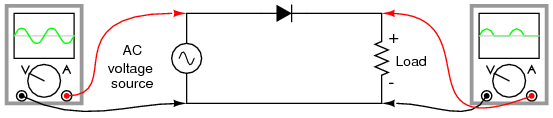
The simplest kind of rectifier circuit is the half-wave rectifier. It only allows one half of an AC waveform to pass through to the load. Half-wave rectification is insufficient for the task. The harmonic content(signal noise) of the rectifier’s output waveform is very large and consequently difficult to filter. Furthermore, the AC power source only supplies power to the load one half every full cycle, meaning that half of its capacity is unused.
2). Full wave Rectifier
If we need to rectify AC power to obtain the full use of both half-cycles of the sine wave, a different rectifier circuit configuration must be used. Such a circuit is called a full-wave rectifier.
In full wave rectifier, we have two configuration:-
a). Center-tap design Full wave rectifier
b). Bridge design Full wave rectifier
Assumption:- Here. the direction given in the following figure, is the direction of flow of Electron. The flow of current will be opposite to direction of flow of electron.
a). Center-tap design Full wave rectifier

This circuit’s operation is easily understood one half-cycle at a time. Consider the first half-cycle, when the source voltage polarity is positive (+) on top and negative (-) on bottom. At this time, only the top diode is conducting(i.e Short Circuit); the bottom diode is blocking(i.e. Open circuit) current, and the load “sees” the first half of the sine wave, positive on top and negative on bottom. Only the top half of the transformer’s secondary winding carries current during this half-cycle.
 |
| Full-wave center-tap rectifier: Top half of secondary winding conducts during positive half-cycle of input, delivering positive half-cycle to load |
During the next half-cycle, the AC polarity reverses. Now, the other diode and the other half of the transformer’s secondary winding carry current while the portions of the circuit formerly carrying current during the last half-cycle sit idle. The load still “sees” half of a sine wave, of the same polarity as before: positive on top and negative on bottom.
 |
| Full-wave center-tap rectifier: During negative input half-cycle, bottom half of secondary winding conducts, delivering a positive half-cycle to the load. |
b). Bridge design Full wave rectifier
Most popular full-wave rectifier design exists, and it is built around a four-diode bridge configuration. For obvious reasons, this design is called a full-wave bridge.
 fig. 2(Full-wave bridge rectifier: Electron flow for negative half-cycles)

Most popular full-wave rectifier design exists, and it is built around a four-diode bridge configuration. For obvious reasons, this design is called a full-wave bridge.
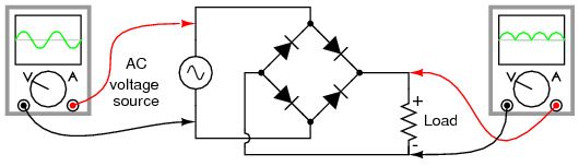 |
| Full wave bridge rectifier |
Current directions for the full-wave bridge rectifier circuit are as shown in Figure 1 for positive half-cycle and Figure 2 for negative half-cycles of the AC source waveform. Note that regardless of the polarity of the input, the current flows in the same direction through the load. That is, the negative half-cycle of source is a positive half-cycle at the load. The current flow is through two diodes in series for both polarities. Thus, two diode drops of the source voltage are lost (0.7·2=1.4 V for Si) in the diodes. This is a disadvantage compared with a full-wave center-tap design. This disadvantage is only a problem in very low voltage power supplies.
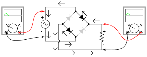 |
| Fig. 1(Full-wave bridge rectifier: Electron flow for positive half-cycles) |
fig. 2(Full-wave bridge rectifier: Electron flow for negative half-cycles)The Smoothing Capacitor
We saw in the previous section that the single phase half-wave rectifier produces an output wave every half cycle and that it was not practical to use this type of circuit to produce a steady DC supply. The full-wave bridge rectifier however, gives us a greater mean DC value (0.637 Vmax) with less superimposed ripple while the output waveform is twice that of the frequency of the input supply frequency.
We can improve the average DC output of the rectifier while at the same time reducing the AC variation of the rectified output by using smoothing capacitors to filter the output waveform. Smoothing or reservoir capacitors connected in parallel with the load across the output of the full wave bridge rectifier circuit increases the average DC output level even higher as the capacitor acts like a storage device as shown below.
Full-wave Rectifier with Smoothing Capacitor
The smoothing capacitor converts the full-wave rippled output of the rectifier into a more smooth DC output voltage.we now run the Partsim Simulator Circuit in order to see the effect of smoothing capacitor.
That's all for this session, I hope you have learnt something new today. If you have any doubt regarding the topic, then please comment.
Thank you.
No comments:
Post a Comment