Friday 30 June 2017

Kirchhoff's Circuit Law

Blog number:-016
Hello Everybody,
Well, I hope you all will be fine.

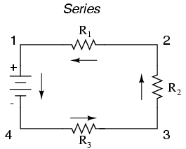
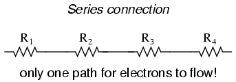
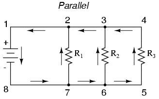
Yesterday we had  discussed on the way of connecting Electric components i.e. Series and Parallel CircuitToday, in this session we are going to discuss about a very fundamental law called Kirchhoff's Circuit Law.

Kirchhoffs Circuit Law:-


         We saw in the Blog number:-015 that a single equivalent resistance, ( Requ.) can be found when two or more resistors are connected together in either series, parallel or combinations of both, and that these circuits obey Ohm’s Law.
However, sometimes in complex circuits such as bridge or T networks, we can not simply use Ohm’s Law alone to find the voltages or currents circulating within the circuit. For these types of calculations we need certain rules which allow us to obtain the circuit equations and for this we can use Kirchhoffs Circuit Law.
      Gustav Kirchhoff developed a pair or set of rules or laws which deal with the conservation of current and energy within electrical circuits. These two rules are commonly known as: Kirchhoffs Circuit Laws with one of Kirchhoffs laws dealing with the current flowing around a closed circuit, Kirchhoffs Current Law, (KCL) while the other law deals with the voltage sources present in a closed circuit, Kirchhoffs Voltage Law, (KVL).

Kirchhoffs First Law – The Current Law, (KCL)

            Kirchhoffs Current Law or KCL, states that the “total current or charge entering a junction or node is exactly equal to the charge leaving the node as it has no other place to go except to leave, as no charge is lost within the node.
        In other words the algebraic sum of all the currents entering and leaving a node must be equal to zero, I(exiting) + I(entering) = 0. This idea by Kirchhoff is commonly known as the Conservation of Charge.

Kirchhoffs Current Law

                               kirchhoffs current law
 
Here, the 3 currents entering the node, I1, I2, I3 are all positive in value and the 2 currents leaving the node, I4 and I5 are negative in value. Then this means we can also rewrite the equation as;
I1 + I2 + I3 – I4 – I5 = 0
The term Node in an electrical circuit generally refers to a connection or junction of two or more current carrying paths or elements such as cables and components. Also for current to flow either in or out of a node a closed circuit path must exist. We can use Kirchhoff’s current law when analyzing parallel circuits.

Kirchhoffs Second Law – The Voltage Law, (KVL)

             Kirchhoffs Voltage Law or KVL, states thatin any closed loop network, the total voltage around the loop is equal to the sum of all the voltage drops within the same loop” which is also equal to zero.
      In other words the algebraic sum of all voltages within the loop must be equal to zero. This idea by Kirchhoff is known as the Conservation of Energy.

Kirchhoffs Voltage Law

                      kirchhoffs voltage law
 
Starting at any point in the loop continue in the same direction noting the direction of all the voltage drops, either positive or negative, and returning back to the same starting point. It is important to maintain the same direction either clockwise or anti-clockwise or the final voltage sum will not be equal to zero. We can use Kirchhoff’s voltage law when analyzing series circuits.
When analyzing either DC circuits or AC circuits using Kirchhoffs Circuit Laws a number of definitions and terminologies are used to describe the parts of the circuit being analysed such as: node, paths, branches, loops and meshes. These terms are used frequently in circuit analysis so it is important to understand them.
Common DC Circuit Theory Terms:
  • • Circuit – a circuit is a closed loop conducting path in which an electrical current flows.
  • • Path – a single line of connecting elements or sources.
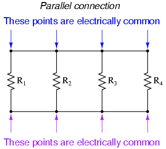
  • • Node – a node is a junction, connection or terminal within a circuit were two or more circuit elements are connected or joined together giving a connection point between two or more branches. A node is indicated by a dot.
  • • Branch – a branch is a single or group of components such as resistors or a source which are connected between two nodes.
  • • Loop – a loop is a simple closed path in a circuit in which no circuit element or node is encountered more than once.
  • • Mesh – a mesh is a single open loop that does not have a closed path. There are no components inside a mesh.

  • Note that:
        Components are said to be connected together in Series if the same current value flows through all the components.
        Components are said to be connected together in Parallel if they have the same voltage applied across them.
So that's all for this session. If you have any doubt related to the topic, please comment.
Thank you.


Thursday 29 June 2017

Series and Parallel Circuits

Blog number:-015
Hello everybody, 
Well, I hope you all will be fine.

Today, we are going to discuss about one of the most basic concept of electricity, i.e. Series and Parallel circuits. It's application is everywhere in the field of Electrical and Electronics.

Introduction:-
                             Image result for series and parallel connection
         Circuits consisting of just one battery and one load resistance are very simple to analyze, but they are not often found in practical applications. Usually, we find circuits where more than two components are connected together. There are two basic ways in which the components of an electric circuits(such as Resistor, Inductor, Capacitor) can be connected.
1). Series Connection
2). Parallel Connection

1). Series Connection
                                       
             In a series circuit, the current through each of the components is the same, and the voltage across the circuit is the sum of the voltages across each componentWith simple series circuits, all components are connected end-to-end to form only one path for electrons to flow through the circuit.
             Here, we have three resistors (labeled R1, R2, and R3), connected in a long chain from one terminal of the battery to the other. (It should be noted that the subscript labeling—those little numbers to the lower-right of the letter “R”—are unrelated to the resistor values in ohms. They serve only to identify one resistor from another.) The defining characteristic of a series circuit is that there is only one path for electrons to flow
               The basic idea of a “series” connection is that components are connected end-to-end in a line to form a single path for electrons to flow:
                                  

       Series circuits are sometimes called current-coupled or daisy chain-coupled

Current
The current in a series circuit goes through every component in the circuit. Therefore, all of the components in a series connection carry the same current. There is only one path in a series circuit in which the current can flow.
In a series circuit the current is the same for all of the elements.

Resistors

The total resistance of resistors in series is equal to the sum of their individual resistances:
This is a diagram of several resistors, connected end to end, with the same amount of current through each.

Inductors 

Inductors follow the same law, in that the total inductance of non-coupled inductors in series is equal to the sum of their individual inductances:
A diagram of several inductors, connected end to end, with the same amount of current going through each.


Capacitor

Capacitors follow the same law using the reciprocals. The total capacitance of capacitors in series is equal to the reciprocal of the sum of the reciprocals of their individual capacitances:
A diagram of several capacitors, connected end to end, with the same amount of current going through each.
.

Switches

Two or more switches in series form a logical AND; the circuit only carries current if all switches are closed.

Cells and batteries

A battery is a collection of electrochemical cells. If the cells are connected in series, the voltage of the battery will be the sum of the cell voltages. For example, a 12 volt car battery contains six 2-volt cells connected in series. Some vehicles, such as trucks, have two 12 volt batteries in series to feed the 24 volt system.

2). Parallel Connection
                                     
       In parallel circuitsall components are connected between the same two sets of electrically common points, creating multiple paths for electrons to flow from one end of the battery to the other.In a parallel circuit, the voltage across each of the components is the same, and the total current is the sum of the currents through each component.
         Here, we have three resistors, but this time they form more than one continuous path for electrons to flow. There’s one path from 8 to 7 to 2 to 1 and back to 8 again. There’s another from 8 to 7 to 6 to 3 to 2 to 1 and back to 8 again. And then there’s a third path from 8 to 7 to 6 to 5 to 4 to 3 to 2 to 1 and back to 8 again. Each individual path (through R1, R2, and R3) is called a branch.
The defining characteristic of a parallel circuit is that all components are connected between the same set of electrically common points. Looking at the schematic diagram, we see that points 1, 2, 3, and 4 are all electrically common. So are points 8, 7, 6, and 5. Note that all resistors as well as the battery are connected between these two sets of points.
          The basic idea of a “parallel” connection  is that all components are connected across each other’s leads. There are many paths for electrons to flow, but only one voltage across all components:
                            
       If two or more components are connected in parallel they have the same potential difference (voltage) across their ends. The potential differences across the components are the same in magnitude, and they also have identical polarities. The same voltage is applicable to all circuit components connected in parallel. The total current is the sum of the currents through the individual components .

Voltage

In a parallel circuit the voltage is the same for all elements.

Current

The current in each individual resistor is found by Ohm's law. Factoring out the voltage gives
.

Resistors

To find the total resistance of all components, add the reciprocals of the resistances  of each component and take the reciprocal of the sum. Total resistance will always be less than the value of the smallest resistance:
A diagram of several resistors, side by side, both leads of each connected to the same wires.
.

Inductors

Inductors follow the same law, in that the total inductance of non-coupled inductors in parallel is equal to the reciprocal of the sum of the reciprocals of their individual inductances:
A diagram of several inductors, side by side, both leads of each connected to the same wires.
.

Capacitors

The total capacitance of capacitors in parallel is equal to the sum of their individual capacitances:
A diagram of several capacitors, side by side, both leads of each connected to the same wires.
.
The working voltage of a parallel combination of capacitors is always limited by the smallest working voltage of an individual capacitor.

Switches

Two or more switches in parallel form a logical OR; the circuit carries current if at least one switch is closed. 

Cells and batteries

If the cells of a battery are connected in parallel, the battery voltage will be the same as the cell voltage but the current supplied by each cell will be a fraction of the total current. For example, if a battery comprises four identical cells connected in parallel and delivers a current of 1 ampere.  Some solar electric systems have batteries in parallel to increase the storage capacity; a close approximation of total amp-hours is the sum of all batteries in parallel.
So. that's all for this session. If you have any doubt related to the topic, please comment.
Thank you.

Monday 26 June 2017

Rectifier

Blog number:-012
Hello Everybody, Very Good morning to all of you. I hope you all will be fine.

Today, we are going to discuss about Rectifier Circuit(Using Diode). But before starting the discussion on rectifier, let us have a short discussion on Diode.
     
     Diode is an Unidirectional device which works only in one direction. i.e. when anode terminal of diode is connected to positive terminal of power source and cathode terminal of diode is connected to negative terminal of power source, then diode works as an short circuit and resistance become ideally zero and maximum current flow through the circuit.
Or when anode terminal of diode is connected to negative terminal of power source and cathode terminal of diode is connected to positive terminal of power source, then diode works as an open circuit and resistance is maximum and no current flow through circuit.
(Assumption- the value of voltage power source >0.7v).

Now, let us begin our Discussion on Rectifier.

Rectifier
       A rectifier is an electrical device that converts alternating current (AC), which periodically reverses direction, to direct current (DC), which flows in only one direction. The process is known as rectification.Rectifiers have many uses, but are often found serving as components of DC power supplies and high-voltage direct current power transmission systems. Rectification may serve in roles other than to generate direct current for use as a source of power. 
        Because of the alternating nature of the input AC sine wave, the process of rectification alone produces a DC current that, though unidirectional, consists of pulses of current. Many applications of rectifiers, such as power supplies for radio, television and computer equipment, require a steady constant DC current (as would be produced by a battery). In these applications the output of the rectifier is smoothed by an electronic filter (usually a capacitor) to produce a steady current.

         Now we come to the most popular application of the diode: rectification.Simply defined, rectification is the process of converting  alternating current (AC) to direct current (DC). This involves a device that only allows one-way flow of electrons. As we have seen, this is exactly what a semiconductor diode does. 

      Types Of Rectifier
         We have two types of rectifier based on the way the diodes are connected. 
          1). Half wave Rectifier
          2). Full wave Rectifier

1). Half Wave Rectifier

Half wave Rectifier
   The simplest kind of rectifier circuit is the half-wave rectifier. It only allows one half of an AC waveform to pass through to the loadHalf-wave rectification is insufficient for the task. The harmonic content(signal noise) of the rectifier’s output waveform is very large and consequently difficult to filter. Furthermore, the AC power source only supplies power to the load one half every full cycle, meaning that half of its capacity is unused

 2). Full wave Rectifier
        If we need to rectify AC power to obtain the full use of both half-cycles of the sine wave, a different rectifier circuit configuration must be used. Such a circuit is called a full-wave rectifier. 
     In full wave rectifier, we have two configuration:-
      a). Center-tap design Full wave rectifier
      b). Bridge design Full wave rectifier

Assumption:- Here. the direction given in the following figure, is the direction of flow of Electron. The flow of current will be opposite to direction of flow of electron.

      a). Center-tap design Full wave rectifier


    This circuit’s operation is easily understood one half-cycle at a time. Consider the first half-cycle, when the source voltage polarity is positive (+) on top and negative (-) on bottom. At this time, only the top diode is conducting(i.e Short Circuit); the bottom diode is blocking(i.e. Open circuit) current, and the load “sees” the first half of the sine wave, positive on top and negative on bottom. Only the top half of the transformer’s secondary winding carries current during this half-cycle.
Full-wave center-tap rectifier: Top half of secondary winding conducts during positive half-cycle of input, delivering positive half-cycle to load
    During the next half-cycle, the AC polarity reverses. Now, the other diode and the other half of the transformer’s secondary winding carry current while the portions of the circuit formerly carrying current during the last half-cycle sit idle. The load still “sees” half of a sine wave, of the same polarity as before: positive on top and negative on bottom.
Full-wave center-tap rectifier: During negative input half-cycle, bottom half of secondary winding conducts, delivering a positive half-cycle to the load.


      b). Bridge design Full wave rectifier
Most popular full-wave rectifier design exists, and it is built around a four-diode bridge configuration. For obvious reasons, this design is called a full-wave bridge.
Full wave bridge rectifier
Current directions for the full-wave bridge rectifier circuit are as shown in Figure 1 for positive half-cycle and Figure 2 for negative half-cycles of the AC source waveform. Note that regardless of the polarity of the input, the current flows in the same direction through the load. That is, the negative half-cycle of source is a positive half-cycle at the load. The current flow is through two diodes in series for both polarities. Thus, two diode drops of the source voltage are lost (0.7·2=1.4 V for Si) in the diodes. This is a disadvantage compared with a full-wave center-tap design. This disadvantage is only a problem in very low voltage power supplies.
Fig. 1(Full-wave bridge rectifier: Electron flow for positive half-cycles)
fig. 2(Full-wave bridge rectifier: Electron flow for negative half-cycles)

The Smoothing Capacitor

      We saw in the previous section that the single phase half-wave rectifier produces an output wave every half cycle and that it was not practical to use this type of circuit to produce a steady DC supply. The full-wave bridge rectifier however, gives us a greater mean DC value (0.637 Vmax) with less superimposed ripple while the output waveform is twice that of the frequency of the input supply frequency.
We can improve the average DC output of the rectifier while at the same time reducing the AC variation of the rectified output by using smoothing capacitors to filter the output waveform. Smoothing or reservoir capacitors connected in parallel with the load across the output of the full wave bridge rectifier circuit increases the average DC output level even higher as the capacitor acts like a storage device as shown below.

Full-wave Rectifier with Smoothing Capacitor

full wave rectifier smoothing
The smoothing capacitor converts the full-wave rippled output of the rectifier into a more smooth DC output voltage.we now run the Partsim Simulator Circuit in order to see the effect of smoothing capacitor. 
That's all for this session, I hope you have learnt something new today. If you have any doubt regarding the topic, then please comment.
Thank you. 


Ohm's Law

Hello Everybody,
I hope you all will be fine.

        In this session, we will discuss about Ohm's law. In the Blog number:-001(Resistor), we came to know about a law called Ohm's law. But we had not discussed in detail. So, we will discuss Ohm's law in detail here.

OHM'S LAW
  The relationship between VoltageCurrent and Resistance in any DC electrical circuit was firstly discovered by the German physicist Georg OhmGeorg Ohm found that, at a constant temperature, the electrical current flowing through a fixed linear resistance is directly proportional to the voltage applied across it, and also inversely proportional to the resistance. This relationship between the Voltage, Current and Resistance forms the basis of Ohms Law. 


Ohms Law Relationship

ohms law

      By knowing any two values of the Voltage, Current or Resistance quantities we can use Ohms Law to find the third missing value. Ohms Law is used extensively in electronics formulas and calculations so it is “very important to understand.

To find the Voltage, ( V )

[ V = I x R ]      V (volts) = I (amps) x R (Ω)

To find the Current, ( I )

[ I = V ÷ R ]      I (amps) = V (volts) ÷ R (Ω)

To find the Resistance, ( R )

[ R = V ÷ I ]      R (Ω) = V (volts) ÷ I (amps)

Ohms Law Triangle

                                         ohms law triangle

Transposing the standard Ohms Law equation above will give us the following combinations of the same equation:
ohms law triangle relationship
        Then by using Ohms Law we can see that a voltage of 1V applied to a resistor of 1Ω will cause a current of 1A to flow and the greater the resistance value, the less current that will flow for a given applied voltage. Any Electrical device or component that obeys “Ohms Law” that is, the current flowing through it is proportional to the voltage across it ( I α V ), such as resistors or cables, are said to be “Ohmic” in nature, and devices that do not, such as transistors or diodes, are said to be “Non-ohmic” devices.

Electrical Power in Circuits

     Electrical Power, ( P ) in a circuit is the rate at which energy is absorbed or produced within a circuit. A source of energy such as a voltage will produce or deliver power while the connected load absorbs it. Light bulbs and heaters for example, absorb electrical power and convert it into either heat, or light, or both. The higher their value or rating in watts the more electrical power they are likely to consume.
The quantity symbol for power is P and is the product of voltage multiplied by the current with the unit of measurement being the Watt ( W ). Prefixes are used to denote the various multiples or sub-multiples of a watt, such as: milliwatts (mW = 10-3W) or kilowatts (kW = 103W).

Q is electric charge in coulombs
t is time in seconds
I is electric current in amperes{ i.e. I=(Q/t)}
V is electric potential or voltage in volts
Work done in joules=VQ


Then by using Ohm’s law and substituting for the values of VI and R the formula for electrical power can be found as:

To find the Power (P)

[ P = V x I ]      P (watts) = V (volts) x I (amps)
Also,
[ P = V2 ÷ R ]      P (watts) = V2 (volts) ÷ R (Ω)
Also,
[ P = I2 x R ]      P (watts) = I2 (amps) x R (Ω)
      Again, the three quantities have been superimposed into a triangle this time called a Power Triangle with power at the top and current and voltage at the bottom. Again, this arrangement represents the actual position of each quantity within the Ohms law power formulas.
power triangle
and again, transposing the basic Ohms Law equation above for power gives us the following combinations of the same equation to find the various individual quantities:
power triangle relationship
      So we can see that there are three possible formulas for calculating electrical power in a circuit. If the calculated power is positive, (+P) in value for any formula the component absorbs the power, that is it is consuming or using power. But if the calculated power is negative, (-P) in value the component produces or generates power, in other words it is a source of electrical power such as batteries and generators.

Ohms Law Pie Chart

ohms law pie chart

Ohms Law Example

For the circuit shown below find the Voltage (V), the Current (I), the Resistance (R) and the Power (P).
ohms law circuit
Voltage   [ V = I x R ] = 2 x 12Ω = 24V
Current   [ I = V ÷ R ] = 24 ÷ 12Ω = 2A
Resistance   [ R = V ÷ I ] = 24 ÷ 2 = 12 Ω
Power   [ P = V x I ] = 24 x 2 = 48W
Thank you.