Monday, 26 June 2017

Rectifier

Blog number:-012
Hello Everybody, Very Good morning to all of you. I hope you all will be fine.

Today, we are going to discuss about Rectifier Circuit(Using Diode). But before starting the discussion on rectifier, let us have a short discussion on Diode.
     
     Diode is an Unidirectional device which works only in one direction. i.e. when anode terminal of diode is connected to positive terminal of power source and cathode terminal of diode is connected to negative terminal of power source, then diode works as an short circuit and resistance become ideally zero and maximum current flow through the circuit.
Or when anode terminal of diode is connected to negative terminal of power source and cathode terminal of diode is connected to positive terminal of power source, then diode works as an open circuit and resistance is maximum and no current flow through circuit.
(Assumption- the value of voltage power source >0.7v).

Now, let us begin our Discussion on Rectifier.

Rectifier
       A rectifier is an electrical device that converts alternating current (AC), which periodically reverses direction, to direct current (DC), which flows in only one direction. The process is known as rectification.Rectifiers have many uses, but are often found serving as components of DC power supplies and high-voltage direct current power transmission systems. Rectification may serve in roles other than to generate direct current for use as a source of power. 
        Because of the alternating nature of the input AC sine wave, the process of rectification alone produces a DC current that, though unidirectional, consists of pulses of current. Many applications of rectifiers, such as power supplies for radio, television and computer equipment, require a steady constant DC current (as would be produced by a battery). In these applications the output of the rectifier is smoothed by an electronic filter (usually a capacitor) to produce a steady current.

         Now we come to the most popular application of the diode: rectification.Simply defined, rectification is the process of converting  alternating current (AC) to direct current (DC). This involves a device that only allows one-way flow of electrons. As we have seen, this is exactly what a semiconductor diode does. 

      Types Of Rectifier
         We have two types of rectifier based on the way the diodes are connected. 
          1). Half wave Rectifier
          2). Full wave Rectifier

1). Half Wave Rectifier
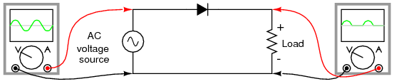
Half wave Rectifier
   The simplest kind of rectifier circuit is the half-wave rectifier. It only allows one half of an AC waveform to pass through to the load. Half-wave rectification is insufficient for the task. The harmonic content(signal noise) of the rectifier’s output waveform is very large and consequently difficult to filter. Furthermore, the AC power source only supplies power to the load one half every full cycle, meaning that half of its capacity is unused. 

 2). Full wave Rectifier
        If we need to rectify AC power to obtain the full use of both half-cycles of the sine wave, a different rectifier circuit configuration must be used. Such a circuit is called a full-wave rectifier. 
     In full wave rectifier, we have two configuration:-
      a). Center-tap design Full wave rectifier
      b). Bridge design Full wave rectifier

Assumption:- Here. the direction given in the following figure, is the direction of flow of Electron. The flow of current will be opposite to direction of flow of electron.

      a). Center-tap design Full wave rectifier


    This circuit’s operation is easily understood one half-cycle at a time. Consider the first half-cycle, when the source voltage polarity is positive (+) on top and negative (-) on bottom. At this time, only the top diode is conducting(i.e Short Circuit); the bottom diode is blocking(i.e. Open circuit) current, and the load “sees” the first half of the sine wave, positive on top and negative on bottom. Only the top half of the transformer’s secondary winding carries current during this half-cycle.
Full-wave center-tap rectifier: Top half of secondary winding conducts during positive half-cycle of input, delivering positive half-cycle to load
    During the next half-cycle, the AC polarity reverses. Now, the other diode and the other half of the transformer’s secondary winding carry current while the portions of the circuit formerly carrying current during the last half-cycle sit idle. The load still “sees” half of a sine wave, of the same polarity as before: positive on top and negative on bottom.
Full-wave center-tap rectifier: During negative input half-cycle, bottom half of secondary winding conducts, delivering a positive half-cycle to the load.


      b). Bridge design Full wave rectifier
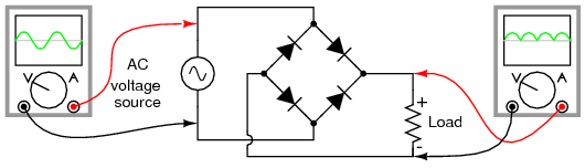
Most popular full-wave rectifier design exists, and it is built around a four-diode bridge configuration. For obvious reasons, this design is called a full-wave bridge.
Full wave bridge rectifier
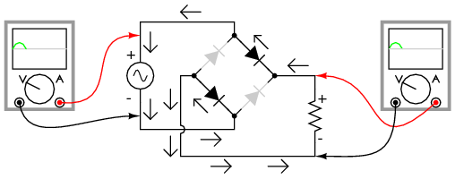
Current directions for the full-wave bridge rectifier circuit are as shown in Figure 1 for positive half-cycle and Figure 2 for negative half-cycles of the AC source waveform. Note that regardless of the polarity of the input, the current flows in the same direction through the load. That is, the negative half-cycle of source is a positive half-cycle at the load. The current flow is through two diodes in series for both polarities. Thus, two diode drops of the source voltage are lost (0.7·2=1.4 V for Si) in the diodes. This is a disadvantage compared with a full-wave center-tap design. This disadvantage is only a problem in very low voltage power supplies.
Fig. 1(Full-wave bridge rectifier: Electron flow for positive half-cycles)
fig. 2(Full-wave bridge rectifier: Electron flow for negative half-cycles)

The Smoothing Capacitor

      We saw in the previous section that the single phase half-wave rectifier produces an output wave every half cycle and that it was not practical to use this type of circuit to produce a steady DC supply. The full-wave bridge rectifier however, gives us a greater mean DC value (0.637 Vmax) with less superimposed ripple while the output waveform is twice that of the frequency of the input supply frequency.
We can improve the average DC output of the rectifier while at the same time reducing the AC variation of the rectified output by using smoothing capacitors to filter the output waveform. Smoothing or reservoir capacitors connected in parallel with the load across the output of the full wave bridge rectifier circuit increases the average DC output level even higher as the capacitor acts like a storage device as shown below.

Full-wave Rectifier with Smoothing Capacitor

full wave rectifier smoothing
The smoothing capacitor converts the full-wave rippled output of the rectifier into a more smooth DC output voltage.we now run the Partsim Simulator Circuit in order to see the effect of smoothing capacitor. 
That's all for this session, I hope you have learnt something new today. If you have any doubt regarding the topic, then please comment.
Thank you. 


Ohm's Law

Hello Everybody,
I hope you all will be fine.

        In this session, we will discuss about Ohm's law. In the Blog number:-001(Resistor), we came to know about a law called Ohm's law. But we had not discussed in detail. So, we will discuss Ohm's law in detail here.

OHM'S LAW
  The relationship between Voltage, Current and Resistance in any DC electrical circuit was firstly discovered by the German physicist Georg Ohm. Georg Ohm found that, at a constant temperature, the electrical current flowing through a fixed linear resistance is directly proportional to the voltage applied across it, and also inversely proportional to the resistance. This relationship between the Voltage, Current and Resistance forms the basis of Ohms Law. 


Ohms Law Relationship

ohms law

      By knowing any two values of the Voltage, Current or Resistance quantities we can use Ohms Law to find the third missing value. Ohms Law is used extensively in electronics formulas and calculations so it is “very important to understand.

To find the Voltage, ( V )

[ V = I x R ]      V (volts) = I (amps) x R (Ω)

To find the Current, ( I )

[ I = V ÷ R ]      I (amps) = V (volts) ÷ R (Ω)

To find the Resistance, ( R )

[ R = V ÷ I ]      R (Ω) = V (volts) ÷ I (amps)

Ohms Law Triangle

                                         ohms law triangle

Transposing the standard Ohms Law equation above will give us the following combinations of the same equation:
ohms law triangle relationship
        Then by using Ohms Law we can see that a voltage of 1V applied to a resistor of 1Ω will cause a current of 1A to flow and the greater the resistance value, the less current that will flow for a given applied voltage. Any Electrical device or component that obeys “Ohms Law” that is, the current flowing through it is proportional to the voltage across it ( I α V ), such as resistors or cables, are said to be “Ohmic” in nature, and devices that do not, such as transistors or diodes, are said to be “Non-ohmic” devices.

Electrical Power in Circuits

     Electrical Power, ( P ) in a circuit is the rate at which energy is absorbed or produced within a circuit. A source of energy such as a voltage will produce or deliver power while the connected load absorbs it. Light bulbs and heaters for example, absorb electrical power and convert it into either heat, or light, or both. The higher their value or rating in watts the more electrical power they are likely to consume.
The quantity symbol for power is P and is the product of voltage multiplied by the current with the unit of measurement being the Watt ( W ). Prefixes are used to denote the various multiples or sub-multiples of a watt, such as: milliwatts (mW = 10-3W) or kilowatts (kW = 103W).

Q is electric charge in coulombs
t is time in seconds
I is electric current in amperes{ i.e. I=(Q/t)}
V is electric potential or voltage in volts
Work done in joules=VQ


Then by using Ohm’s law and substituting for the values of V, I and R the formula for electrical power can be found as:

To find the Power (P)

[ P = V x I ]      P (watts) = V (volts) x I (amps)
Also,
[ P = V2 ÷ R ]      P (watts) = V2 (volts) ÷ R (Ω)
Also,
[ P = I2 x R ]      P (watts) = I2 (amps) x R (Ω)
      Again, the three quantities have been superimposed into a triangle this time called a Power Triangle with power at the top and current and voltage at the bottom. Again, this arrangement represents the actual position of each quantity within the Ohms law power formulas.
power triangle
and again, transposing the basic Ohms Law equation above for power gives us the following combinations of the same equation to find the various individual quantities:
power triangle relationship
      So we can see that there are three possible formulas for calculating electrical power in a circuit. If the calculated power is positive, (+P) in value for any formula the component absorbs the power, that is it is consuming or using power. But if the calculated power is negative, (-P) in value the component produces or generates power, in other words it is a source of electrical power such as batteries and generators.

Ohms Law Pie Chart

ohms law pie chart

Ohms Law Example

For the circuit shown below find the Voltage (V), the Current (I), the Resistance (R) and the Power (P).
ohms law circuit
Voltage   [ V = I x R ] = 2 x 12Ω = 24V
Current   [ I = V ÷ R ] = 24 ÷ 12Ω = 2A
Resistance   [ R = V ÷ I ] = 24 ÷ 2 = 12 Ω
Power   [ P = V x I ] = 24 x 2 = 48W
Thank you.

Sunday, 25 June 2017

AC and DC current

Blog number:-011
Hello Everyone,
Very good morning to all of you, I hope you all will be fine.

          Today, we are going to start Some basics concepts in Electrical and electronics Field. And before starting the main series of blogs, let us discuss today about types of signal in Electrical and Electronics that we generally use. There are particularly  two types of signal that we use in our life(either in form of live wire or in form of storage form). i.e 1) AC and, 2) DC.
       So, before discussing the AC and DC Currents. let us have a short discussion on Voltage and Electric Current.Voltage is the pressure from an electrical circuit's power source that pushes charged electrons (current) through a conducting loop, enabling them to do work.An electric current is a flow of electric charge.

So, let us now discuss about AC and DC.


AC Current(Alternating Current)
    Alternating current describes the flow of charge that changes direction periodically. As a result, the voltage level also reverses along with the current. AC is used to deliver power to houses, office buildings, etc.
AC  has some useful properties, such as being able to convert voltage levels with a single component (a transformer).


Generating AC
      AC can be produced using a device called an alternator(used in power plants) and Electric Generator(used for household purpose). This device is a special type of electrical generator designed to produce alternating current. The frequency of alternating current is 50Hz or 60Hz depending upon the country.

Waveform

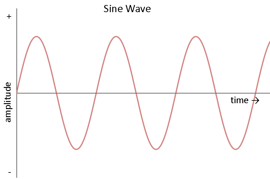
         AC can come in a number of forms(such ac Sine Wave, Square Wave, Triangle Wave), as long as the voltage and current are alternating. If we hook up an oscilloscope to a circuit with AC and plot its voltage over time, we might see a number of different waveform. The most common type of AC is the sine wave. The AC in most homes and offices have an oscillating voltage that produces a sine wave.
alt text

DC Current(Direct Current)
     DC provides a constant voltage or current and always flow in one direction(i.e. either in positive direction or in negative direction). DC is used to deliver power to Cell phones, Hybrid electric Vehicle  etc.
  DC  has not properties of being able to convert voltage levels with a single component like AC does.
The frequency of direct current is zero.


Generating DC

Dc cannot be generated directly and is always being converted from AC to DC. DC can be generated in a number of ways:
  • An AC generator equipped with a device called a “commutator” can produce direct current
  • Use of a device called a “rectifier” that converts AC to DC
  • Batteries provide DC, which is generated from a chemical reaction inside of the battery.
Waveform
     DC is defined as the “unidirectional” flow of current; current only flows in one direction. Voltage and current can vary over time so long as the direction of flow does not change. To simplify things, we will assume that voltage is a constant.

So, that's all for this session. If you have any problem regarding the topic, please feel free to comment.
Thank you 
Have a good day ahead.